The French company ATI ENVIRONNEMENT took part in the 9th edition of “Save the Planet” Waste Management and Recycling exhibition that took place in the end of March in Sofia.
The company specialized in treatment of hospital, animal and industrial wastes presents their flue gas treatment system, that can be equipped to any kind of their incinerators in the aim to be in accordance with EU directives regarding the incineration of wastes and the pollutants emission.
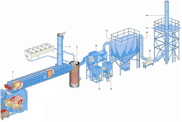
See a short technical description of the system, including a schematic layout
The flue gas treatment system will meet the European standards of emission gas from waste incineration plant Directive 2000/76/CE and 2010/75/CE.
The flue gas treatment system is composed of an emergency by-pass, a heat exchanger, two dry reactors and ceramic filters.
By-pass system for gases evacuation (security)
The by-pass for gases evacuation [7] is placed at the top of the post-combustion chamber [5], as a chimney cover which is made in steel sheet.
The metallic chimney is made of heavy steel sheet with internal refractory lining
The waterproof valve will be controlled by a pneumatic jack.
Reactors and ceramic filtration system
Leaving the Heat Exchanger [8], the flue gases has a temperature between 200 °C to 300 °C and contain pollutants consisting of dusts, HCL, SO2, HF, heavy metal, dioxins and furans
Filtrating system consists in injecting two neutralizing substances: hydrated lime to neutralize acids like HCl, S02, HF, and active carbon to absorb dioxins and furans
These neutralizing chemical products are stored in two separated hoppers [12 & 13]. They are injected into each reactor [10] which affects a gas/neutralizer mixture to purify the pollutant.
The main dust particles are already separated by the centrifugal strength in the inlet of the ceramic filter [14]
Then the gaseous stream uniformly vacuums the filtration parts. The dust as well as the neutralizers stay on the filtration parts, while the purified gases go through the elements.
After an adjustable space of time, a compressed air jet is injected inside the elements by the counterblow pulsating cleaning system. This is alternatively achieved by cloth group.
This compressed air jet releases the dust agglomerated over elements into the dust collecting basin situated under the filter housing
After the dust has been entirely filtered out, purified flue gases are drawn out by means of I/D fan through a temperature control valve [16]
Component parts and design:
The dust extraction system featuring a ceramic filter consists of the following elements:
-
Filter housing intended for filter modules
-
Filter modules with ceramic filter elements (module and elements are positioned in such a way that they can be replaced horizontally on the clean air side).
-
Compressed air cleaning system featuring a compressed air reservoir, electromagnetic valves and electronic control.
-
Supporting columns with anchoring bolts
-
Fan's base plate (mounted)
-
Connecting flanges.
Chemical reaction by neutralization
Ca(OH)2 + 2 HCl ----------------------------------- CaCl2 + 2 H2O
Ca(OH)2 + 2 HF ----------------------------------- CaF2 + 2 H20
Ca(OH)2 + SO2 ----------------------------------- CaSO3 + H2O
Ca(OH)2 + SO2 + 0.5 O2 ------------------------ CaSO4 + H2O
Dioxins/Furans (PCDD/PCDF) production
= Carbon (C) in dusts + Oxygen (0) in Gas + Cl (produced from plastics) + T° (250°C – 450°C)
In general, in waste in France, the production of Dioxins/Furans after the boiler: 5 ng/Nm3
Including:
-
2 ng/Nm3 in particle form, eliminated by ceramic filters
-
1 ng/Nm3 in gaseous form, absorbed by active carbon
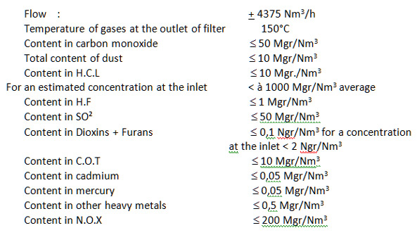
Guarantee of gases emission at the outside of the chimney
Values expressed with 11% o² :